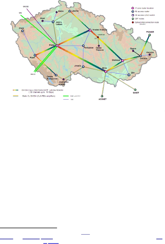
Figure 54: CESNET2 optical topology and technology in 2007
The IP/MPLS CESNET network layer follows the optical transmission topology (see Figure 54).
Within the main DWDM ring PoPs, network backbone routers as the P routers within the MPLS
network topology (Praha, Brno, Olomouc and Hradec Králové) are placed. In the other ones,
access routers as the PE routers, which provides all the functionality and services of backbone
network (MPLS13, EoMPLS, QoS, IPv4/IPv6 unicast, IPv4 multicast routing and NetFlow
statistics), are located. Cisco OSR 7609's with SUP720-3BXL supervisors and WS-X6704 4-
port 10GE LAN PHY cards (as well as some 1GE cards used) are used as the core routers and
provider-side edge routers. (These are designated as "P Routers" and "PE Routers" in the figure).
The small PoPs without the MPLS functionality run Layer 2 and 3 switches (Catalyst 3750) as the
customer equipment (CE) devices. The full network services-capability is achieved by using the
facilities in the PE routers. There are trunks between PE and CE devices and VLANs configured.
For links running Ethernet over MPLS (EoMPLS) the Layer2 services-distribution within the CE
PoPs uses EoMPLS tunnels which are mapped onto VLANs. We also tested and successfully
implemented the multipoint Ethernet services (VPLS) for the METACentrum project (Czech
academic computing and storage Grid) in the CESNET2 backbone network environment (see
13
Short for Multiprotocol Label Switching, an IETF initiative that integrates Layer 2 information about
network links (bandwidth, latency, utilization) into Layer 3 (IP) within a particular autonomous system--or ISP--in
order to simplify and improve IP-packet exchange.
88
 Page1
Page1 Page87
 Page89
 Page177